Creo Sheet Metal Flat Vs Flanged

Sheet Metal Flat States

Creo Parametric 5 0 Enhancements Sheet Metal Flat Reps Youtube

Creo Sheetmetal Extrude Planar Flat And Flange In Sheet Metal Youtube

Creo Sheetmetal Tutorial How To Create Flat Wall Feature Youtube
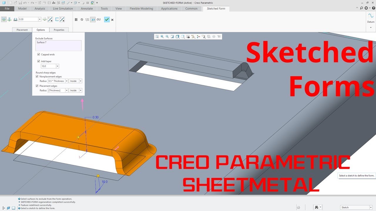
Creo Parametric Sheetmetal Sketched Forms Tutorial Youtube

Engine In Creo 3d Modeling Tutorial Parametric Mechanical Design
Flange i am currently attempting to set up user friendly templates for the various types of v clips i work with and i have a small dilema.
Creo sheet metal flat vs flanged.

Ptc Creo 4 0 Tutorial How To Create Custom Unbend Feature Sheetmetal Youtube
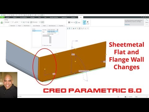
Creo Parametric 6 0 Sheetmetal Flat And Flange Wall Changes Youtube

Creo Parametric Sheetmetal Flattening Methods Flat Pattern Unbend And Flatten Form Youtube

Creo Parametric Sheetmetal Punch Forms Tutorial Youtube
Source : pinterest.com
